This guide will help to do initial setup to a Dragino RS485-LN node: Power on and UART connectivity.
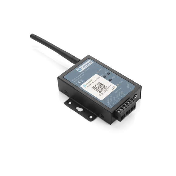
- LoRaWAN Class A & Class C
- 1 x RS485 port (A and B)
- Power Input: 7-24V
- Power adapter is not included
- Datasheet: https://bit.ly/Dragino-RS485-LN
- User manual: v1.3 and Online version
- Document base: From Dragino
1. Pin Mapping
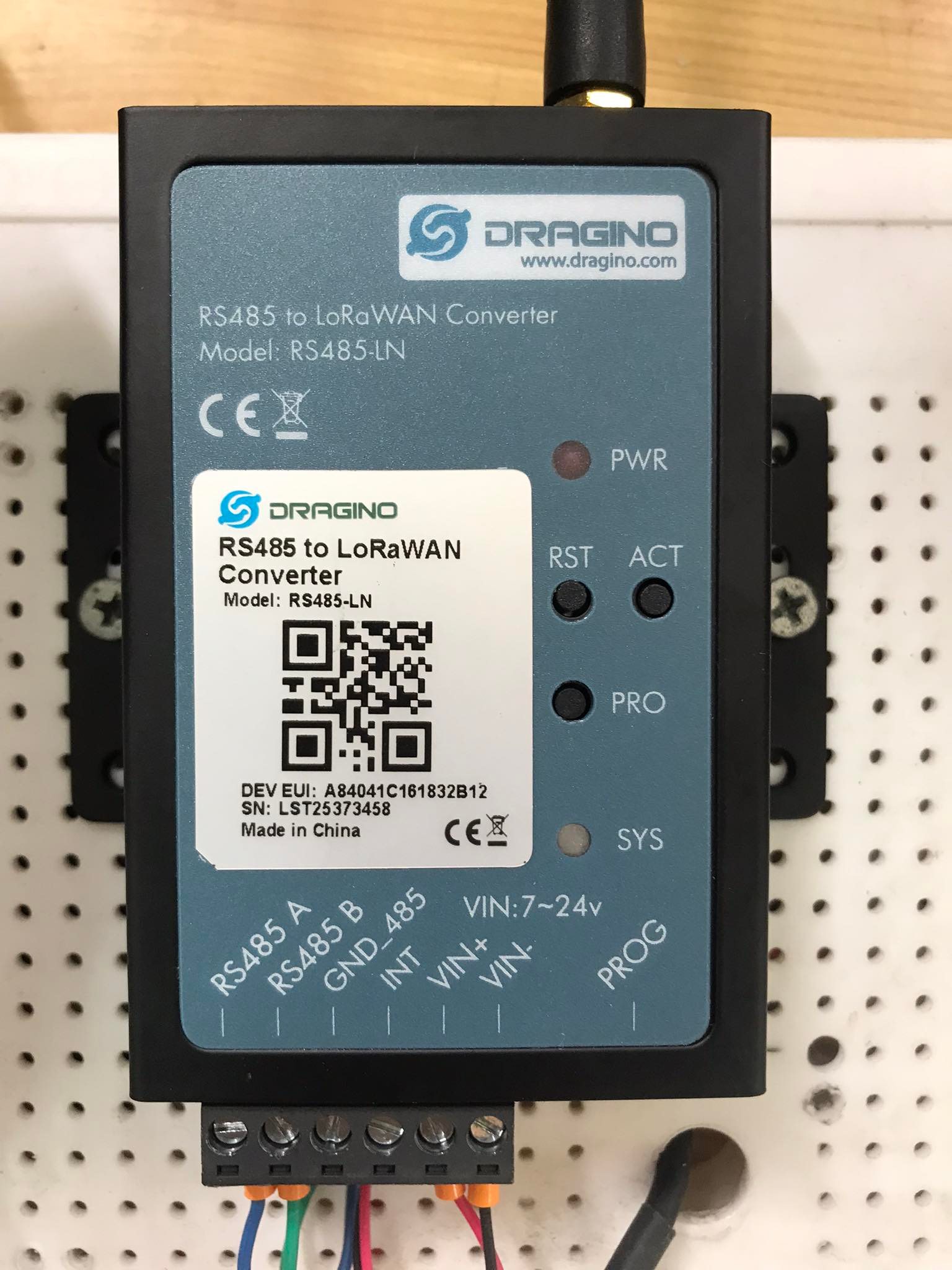
RS485 pins:
- RS485 A: to RS485 A of the RS485 sensor
- RS485 A: to RS485 A of the RS485 sensor
- GND_485 (Optional): To GND of RS485 sensor. This is only required for long RS485 cable.
Power pins:
- VIN+: To VCC+ of the power supply (7-24v). Recommended voltage: 12v or 24v.
- VIN-: To GND of the power supply
Other pins:
- INT: To set interrupt to send an uplink.
- PROG: To connect to UART cable for debugging or uploading firmware
Buttons:
- RST: To reset node
- PRO: To enter flashing mode
- ACT: To send an uplink
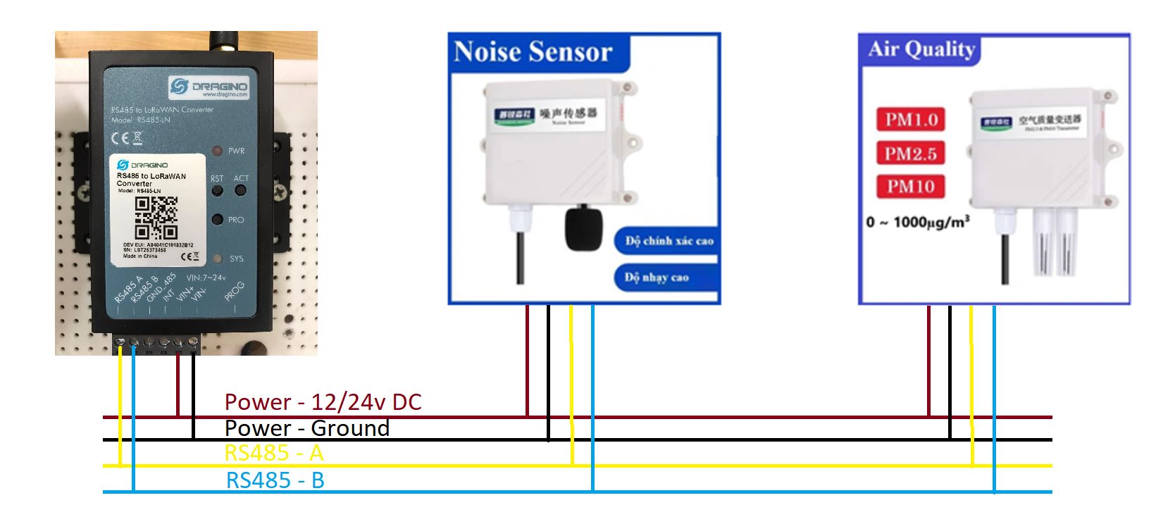
2. Connect to Power and RS485 Sensors
Sample wiring from RS485-LN to multiple RS485 sensors:
- 12vDC or 24vDC adapter is required.
- A and B port of RS485-LN node are wired parallelly to A and B of RS485 sensors.
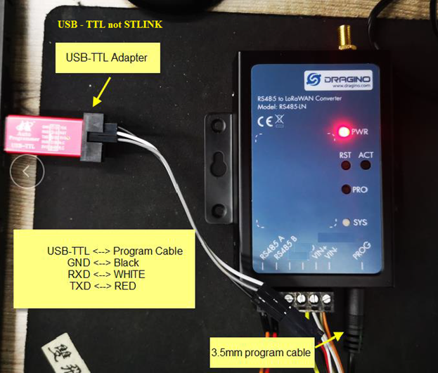
3. Connect UART cable
In the box, there is a 3.5mm program cable.
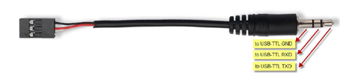
To connect the 3.5mm program cable into PROG port of the node and UART USB into the laptop/PC.
Need help for your projects?
Please chat with us on the red chatbox to get help or discuss about your projects.
Thanks for reaching us.


4. Connect to UART console
Step 1: To open a UART console
Step 2: To open Tera Term and check if the frequency plan is AS923-2 for Vietnam.
Step 3: To check for LoRaWAN information.
Done.