This guide will instruct you to create a DIY LoRaWAN nodes using RAK module.
- The guide is applicable to all RAK modules with a few minor differences.
- The node is compatible with all LoRaWAN servers including Easy LoRaWAN Cloud.
- The node will support LoRaWAN 1.0.3, Class A/B/C and uplink/downlink feature.
- Product link: You can view and buy the RAK3172 Evaluation Board.
- Product Documentation: RAK3172 Evaluation Board and RAK19007 Base Board
- Source code: LoRaWAN_OTAA (Recommended) or LoRaWAN_ABP
Step 1: To purchase a RAK module.
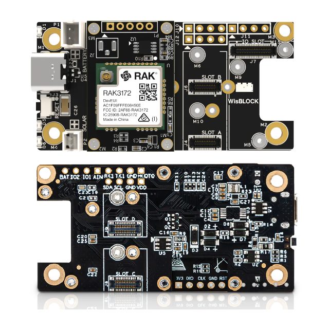
- In this guide, we focus on RAK3172 Evaluation Board.
Step 2: To install Arduino IDE
- We assume you have basic knowledge how to use Arduino IDE.
- Arduino IDE is free and well-known in IoT programming
Step 3: We will use the RAK module as a standalone device. We can do custom code in Arduino for a RAK module in standalone device mode.
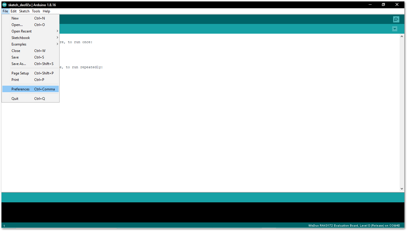
- Open Arduino IDE and go to File > Preferences.
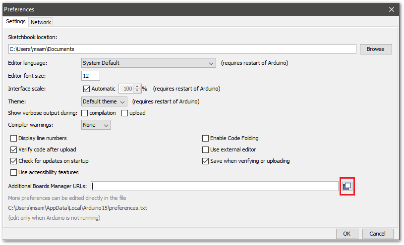
- To add the RAK3172-E to your Arduino Boards list, edit the Additional Board Manager URLs and click the icon, as shown in Figure 5.
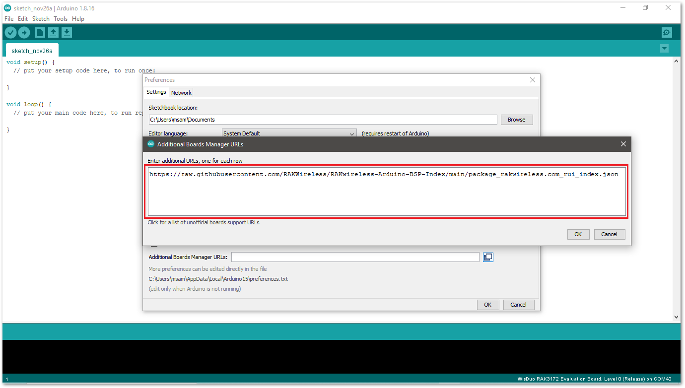
- Copy the URL
https://raw.githubusercontent.com/RAKWireless/RAKwireless-Arduino-BSP-Index/main/package_rakwireless.com_rui_index.jsonand paste it on the field, as shown in Figure 6. If there are other URLs already there, just add them on the next line. After adding the URL, click OK.
- Restart the Arduino IDE.
- Open the Boards Manager from Tools Menu.
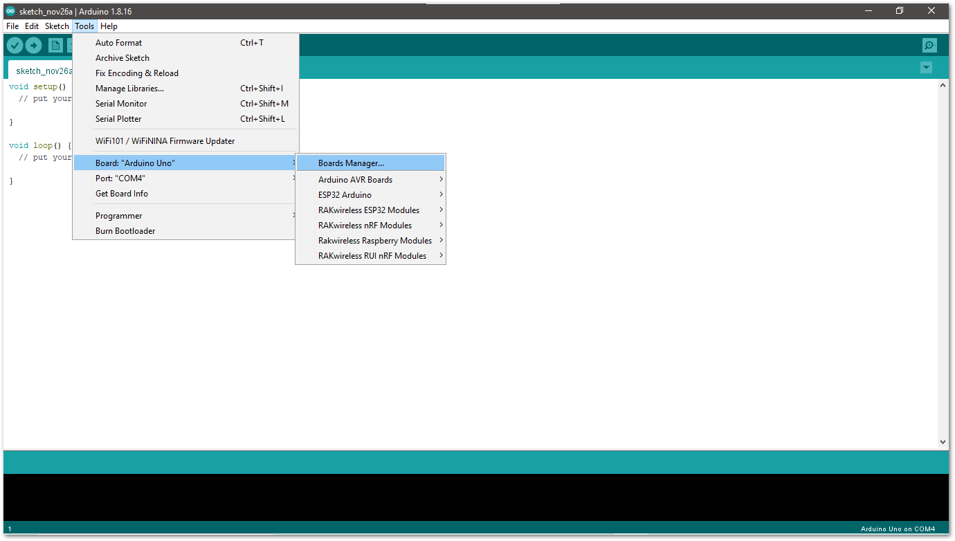
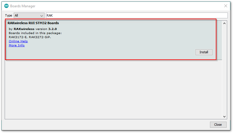
- Write RAK in the search bar, as shown in Figure 8. This will show the available RAKwireless module boards that you can add to your Arduino Board list. Select and install the latest version of the RAKwireless RUI STM32 Boards.
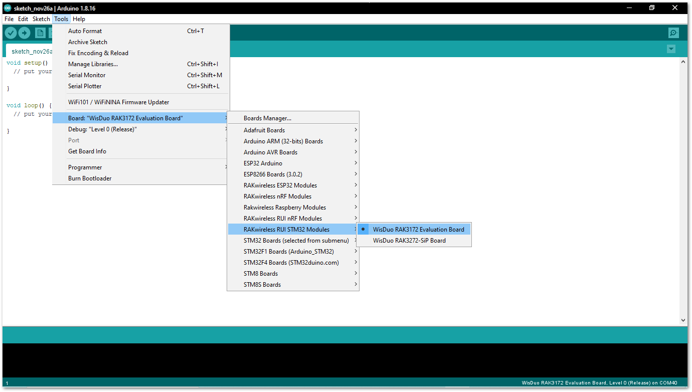
- Once the BSP is installed, select Tools > Boards Manager > RAKWireless RUI STM32 Modules > WisDuo RAK3172 Evaluation Board. The RAK3172 Evaluation board uses RAK3172 WisDuo module.
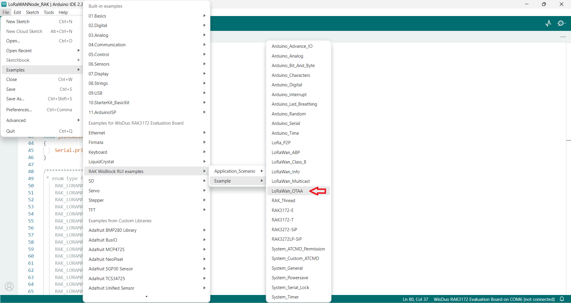
Step 4: To compile and run an example code (LoRaWAN_OTAA) for LoRaWAN node
- Direct link to example source code: LoRaWAN_OTAA (Recommended) or LoRaWAN_ABP
Step 5: You need to change the below information for your node
- OTAA_BAND: This is the frequency plan for LoRaWAN in your country. The supported settings are
RAK_REGION_EU433RAK_REGION_CN470RAK_REGION_RU864RAK_REGION_IN865RAK_REGION_EU868RAK_REGION_US915RAK_REGION_AU915RAK_REGION_KR920RAK_REGION_AS923RAK_REGION_AS923_2RAK_REGION_AS923_3RAK_REGION_AS923_4
- OTAA_DEVEUI: This should be unique. You can copy on the label of the RAK module. This value will be used in later guide.
- OTAA_APPEUI : You can leave this as all zeros. This is not used by Easy LoRaWAN Cloud
- OTAA_APPKEY: You can put any value for this settings. This value will be used in later guide.
Step 6: Put in USB-C cable from your RAK module to your laptop, compile and run the board.
- You should have CH340 driver installed in previous step.
Step 7: To configure your gateways and LoRaWAN server
- You need to configure your commercial LoRaWAN gateways or your DIY LoRaWAN gateways.
- You need to add your LoRaWAN gateway and node to LoRaWAN server or Easy LoRaWAN Cloud in QuickStart guides.
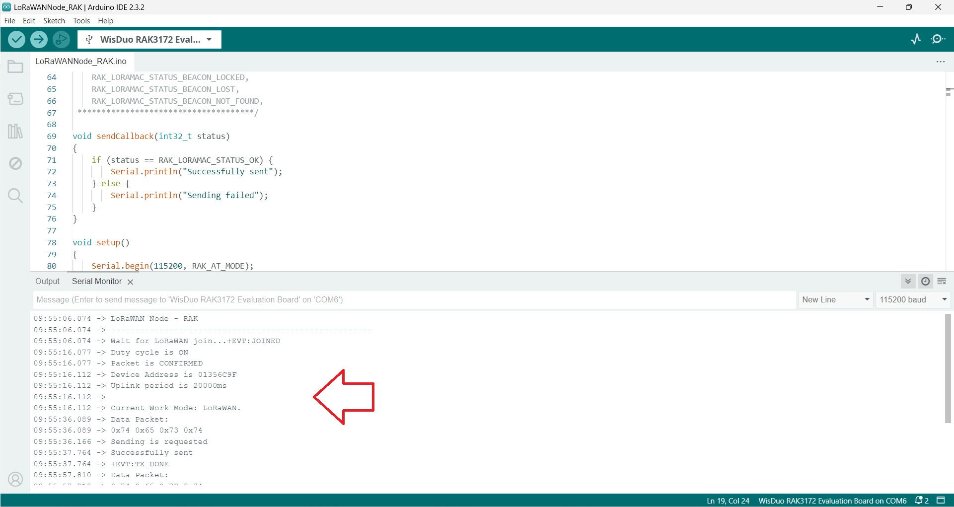
Step 8: Open Serial Monitor in Arduino IDE to see the node joins LoRaWAN and send uplink packets.
Done.
Need help for your projects?
Please chat with us on the red chatbox to get help or discuss about your projects.
Thanks for reaching us.


Hi,
I use Easy LoRaWAN Cloud
I have issue to upload my Adruino code to my RAK3127.
It said unable to detect baudrate.
Do you have any hints?
Thanks a lot.
Hi John,
You may look at this guide to fix the firmware of your RAK module.
Then you can upload your Arduino code again.
https://iotthinks.com/flash-firmware-for-rak-lorawan-modules/
It works now!
Thanks a lot.
Hi,
Do you have some guides to create a DIY LoRaWAN node using STM32 board?
Thanks a lot.
Hi Kevin,
Ok, we will create a guide for STM32 board using STM32CubeIDE and CubeMX this month.
Keep in touch.
Best regards.