This guide will help to do initial setup to a Dragino LT-22222-L node: Power on and UART connectivity.
- Product link: Dragino-LT-22222-L
- LoRaWAN Class A & Class C
- 2 x Digital Input
- 2 x Digital Output
- 2 x Relay Output (AC / DC)
- 2 x 0~20mA Analog Input
- 2 x 0~30V Analog Input
- Power Input 7~24V
- Power adapter is not included
- Datasheet: https://bit.ly/Dragino-LT-22222-L
- User Manual: v1.5.7 and online version
- Document base: From Dragino
1. Initial Setup
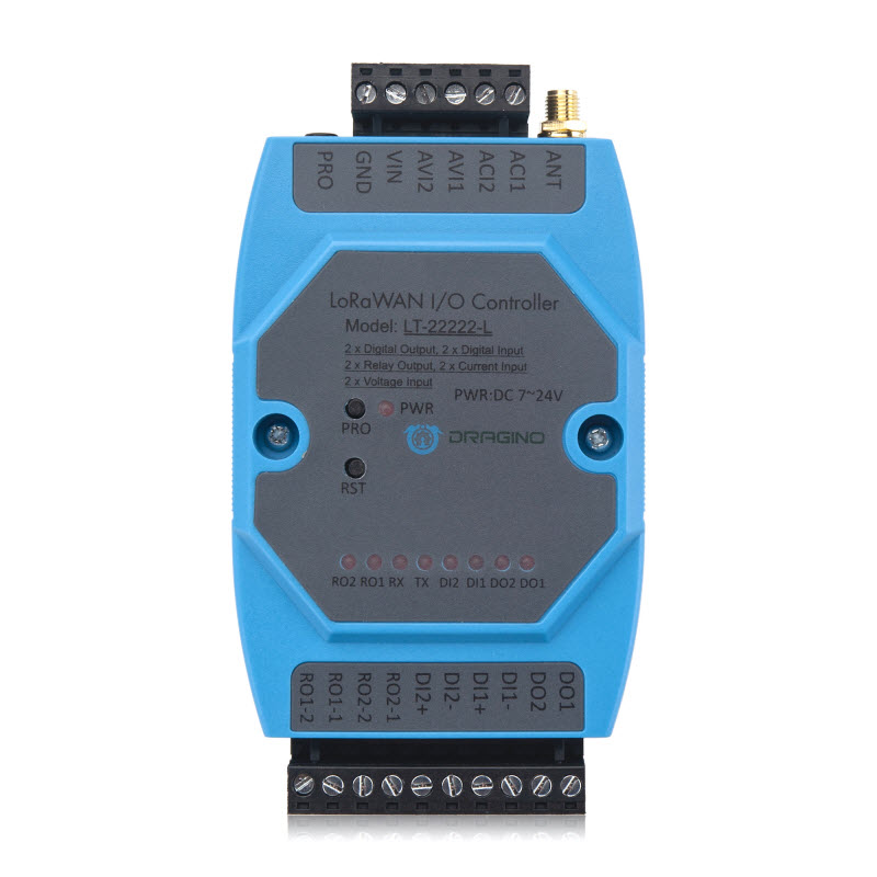
Main pins:
- PRO: To connect to UART cable for debugging or uploading firmware.
- GND: To GND of the power supply
- VIN: To VCC+ of the power supply (7-24v). Recommended voltage: 12v or 24v.
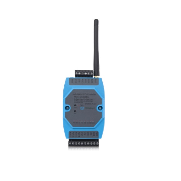
- ANT: To connect to the antenna.
Buttons:
- RST: To reset node
- PRO: To enter flashing mode
Other pins:
- AVI1/2, ACI1/2: To connect to voltage/current (4-20mA) sensors.
- DO1/2: Digital output
- DI1/2: Digital input
- RO1/2: AC/DC Relays. Up to 30V DC or 220v AC.
Need help for your projects?
Please chat with us on the red chatbox to get help or discuss about your projects.
Thanks for reaching us.


2. Connect to UART console (Optional)
Step 1: In the box, there is a 3.5mm program cable.
Step 2: To connect the 3.5mm program cable into PROG port of the node and UART USB into the laptop/PC.
Step 3: To open a UART console
Step 4: To open Tera Term and check if the frequency plan is AS923-2 for Vietnam.
Step 5: To check for LoRaWAN information.
Step 6: To download the codec. It is required in the next guide.
Done.